Oric Atmos Diagnostic harness
Diagnostic board, ROM and harness for the Oric/Atmos 48k computer.
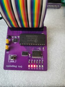
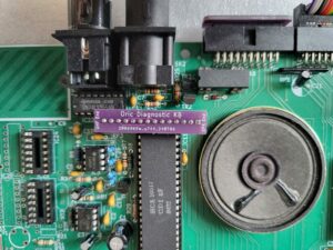
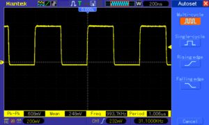
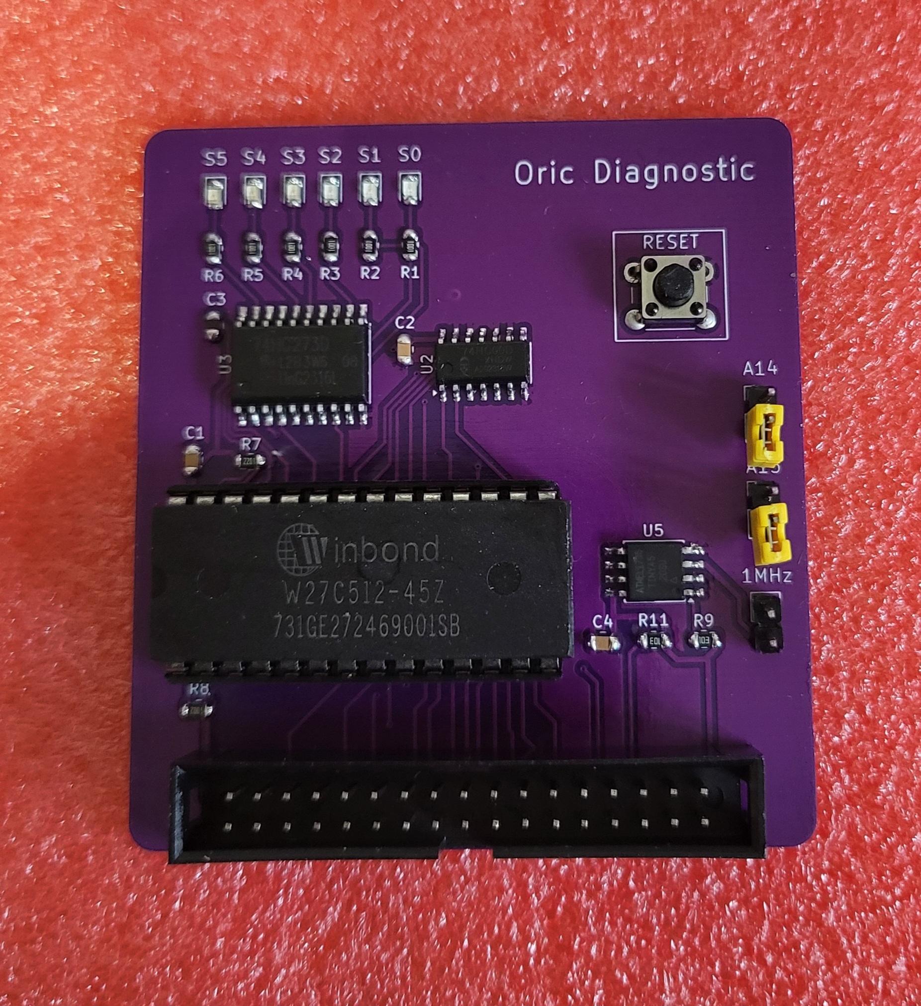
The diagnostic board together with the loopback connectors perform diagnostic tests on the Oric/Atmos using the software written by Mike Brown. The diagnostic board is also based on his design and has been updated with SMD components and a micrcontroller to generate a stable 1MHz clock which can be used as a clock source (See photo)
There are also status LEDs on the board which provide you a visual indication of what the address lines are doing.
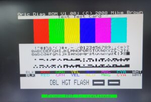
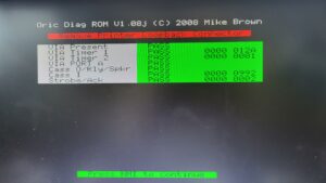
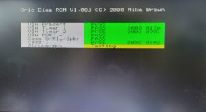
The diagnostic board and software runs the following tests:
- Basic RAM Test
- Full RAM Test
- Basic ULA Test
- Test ULA Test
- HIRES ULA Test
- 6522 VIA Test
- 6522 VIA Timer 1 & 2
- 6522 VIA/Relay/Amp/Speaker
- 8912 PSG Test
Mike has written a excellent manual detailing all the tests and provides troubleshooting steps on test failures.
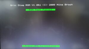
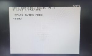
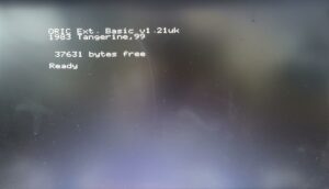
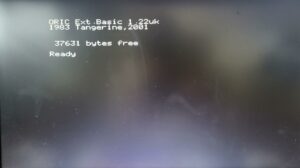
The diagnostic board contains 4 ROMs which are selected using the A14/A15 jumpers:
| ROM | A14 | A15 |
|---|---|---|
| DiagROM 1.08 | disable | disable |
| Oric original ROM v1.1 | enable | disable |
| Pascal’s ROM 1.22 UK | disable | enable |
| Pascal’s ROM 1.21 UK | enable | enable |
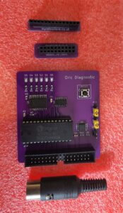
Includes:
- Diagnostic board
- 34 way Ribbon cable
- Keyboard loopback connector
- Printer loopback connector
- Cassette loopback connector
Before using this device download and read through the manual to make sure you understand the operation of the software. (When to insert loopback connects etc)
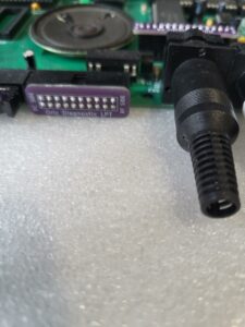
When inserting the loopback connectors make sure that the orientation is correct.
On the keyboard and printer connectors pay attention to the text on the PCB (RF Side – points toward RF Modulator, DC Side – points toward DC plug, SPK End – points toward speaker, UHF End – points toward RF Modulator)
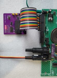
Also make sure when you connect and disconnect the diagnostic board to the Oric using the 34-way ribbon cable that the Oric is powered off
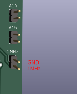
If you want to use the 1Mhz clock provided you can connect a shielded cable (not provided) from the Oric to the 1MHz Pin – see photo for pinout.
