AVR Atmega / ATtiny Fuse Bit Doctor for repairing incorrect fusebits
AVR ATmega / ATtiny Fuse Bit Doctor
Software version 2.11
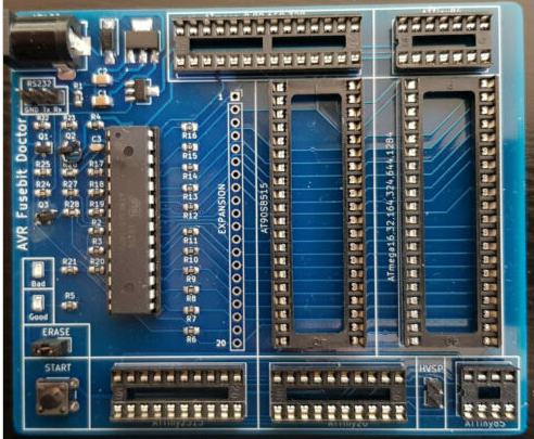
AVR Fusebit Doctor is a device used for repairing incorrect fuse settings for the ATmega and ATtiny family of AVR microcontrollers.
A common mistake is setting the incorrect value for CKSEL or disabling SPI programming which causes the microcontroller to appear dead.
You will receive:
- 1 x PCB (Assembled and tested)
The instruction manual can be downloaded here
Please read these instructions carefully to ensure this is what you require and will work for you.
The board will need to be powered by a 13-20V DC power supply (Power Supply and DC cable/plug not supplied)
DC Connector is a 5.5×2.1mm DC plug, center pin GND
This design is based off the work of the original project by Manekinen, and then work resumed by SukkoPera.
To obtain the latest updates and firmware Google: github sukkopera fusebit doctor
(eBay does not allow posting of links)
Supported chips
Some of the below chips (mostly SMD’s) will require a custom built adapter to work with the doctor (Adapter not included).
Code to this point supports 145 chips, but not all have been fully tested.
1kB
AT90s1200, ATtiny11, ATtiny12, ATtiny13/A, ATtiny15
2kB
ATtiny2313/A, ATtiny24/A, ATtiny26, ATtiny261/A, ATtiny28, AT90s2333, ATtiny22, ATtiny25, AT90s2313, AT90s2323, AT90s2343
4kB
ATmega48/A, ATmega48P/PA, ATtiny461/A, ATtiny43U, ATtiny4313, ATtiny44/A, ATtiny48, AT90s4433, AT90s4414, AT90s4434, ATtiny45
8kB
ATmega8515, ATmega8535, ATmega8/A, ATmega88/A, ATmega88P/PA, AT90pwm1, AT90pwm2, AT90pwm2B, AT90pwm3, AT90pwm3B, AT90pwm81, AT90usb82, ATtiny84, ATtiny85, ATtiny861/A, ATtiny87, ATtiny88, AT90s8515, AT90s8535
16kB
ATmega16/A, ATmega16U2, ATmega16U4, ATmega16M1, ATmega161, ATmega162, ATmega163, ATmega164A, ATmega164P/PA, ATmega165A/P/PA, ATmega168/A, ATmega168P/PA, ATmega169A/PA, ATtiny167, AT90pwm216, AT90pwm316, AT90usb162
32kB
ATmega32/A, ATmega32C1, ATmega323/A, ATmega32U2, ATmega32U4, ATmega32U6, ATmega32M1, ATmega324A, ATmega324P, ATmega324PA, ATmega325, ATmega3250, ATmega325A/PA, ATmega3250A/PA, ATmega328, ATmega328P, ATmega329, ATmega3290, ATmega329A/PA, ATmega3290A/PA, AT90can32
64kB
ATmega64/A, ATmega64C1, ATmega64M1, ATmega649, ATmega6490, ATmega649A/P, ATmega6490A/P, ATmega640, ATmega644/A, ATmega644P/PA, ATmega645, ATmega645A/P, ATmega6450, ATmega6450A/P, AT90usb646, AT90usb647, AT90can64
128kB
ATmega103, ATmega128/A, ATmega1280, ATmega1281, ATmega1284, ATmega1284P, AT90usb1286, AT90usb1287, AT90can128
256kB
ATmega2560, ATmega2561
Usage
Check through the table below to determine which socket to install the microcontroller in.
Take care to the the orientation correct.
Size
|
|
Chip |
Socket |
|
1kB |
AT90s1200 |
5 |
|
1kB |
ATtiny11, ATtiny12, ATtiny13, ATtiny15 |
7 |
|
2kB |
ATtiny2313 |
5 |
|
2kB |
ATtiny24 |
2 |
|
2kB |
ATtiny26, ATtiny261 |
6 |
|
2kB |
ATtiny22 , ATtiny25 |
7 |
|
2kB |
AT90s2313 |
5 |
|
2kB |
AT90s2323, AT90s2343 |
7 |
|
4kB |
ATtiny461 |
6 |
|
4kB |
ATtiny4313 |
5 |
|
4kB |
ATtiny44 |
2 |
|
4kB |
ATtiny48, ATtiny45, AT90s4433 |
1 |
|
4kB |
AT90s4414 |
3 |
|
8kB |
ATmega8515. ATmega8535 |
4 |
|
8kB |
ATmega8, ATmega88 |
1 |
|
8kB |
ATtiny84 |
2 |
|
8kB |
ATtiny84 |
7 |
|
8kB |
ATtiny861 |
6 |
|
8kB |
AT90s8515 |
3 |
|
8kB |
AT90s8535 |
4 |
|
8kB |
ATmega16 |
4 |
|
8kB |
ATmega161, ATmega162 |
3 |
|
16kB |
ATmega163, ATmega164 |
4 |
|
16kB |
ATmega168 |
1 |
|
32kB |
ATmega32. ATmega323, ATmega324 |
4 |
|
32kB |
ATmega328 |
1 |
|
64kB |
ATmega644 |
4 |
|
128kB |
ATmega1284 |
4 |
The ERASE jumper allows doctor to erase whole flash and eeprom memory. If disabled the doctor will never erase the memory but may not fix the device if the lockbits are enabled.
If fixing HVSP proccessors (ATtiny85 / ATtiny85) select the HVSP jumper, otherwise this jumper should be removed.
Apply power to the DC connector. This needs to be 12V or greater as 12V is needed for high voltage programming. The doctor has a 12V regulator fitted so you can use more than 12V.
Recommended to supply 13-20V DC
After inserting the dead microntroller in one of the sockets (Only use one socket at a time), press the START button and doctor will initiate the parallel or serial high-voltage programming mode.
The device signature is checked and if supported the fusebits will be reset. After fusebits are verified, the LEDs will flash.
LED explanation
- Green – dead microcontroller is fixed, fusebits repaired.
- Red – signature problem. Unable to read / No device in socket / No signature in database.
- Green flashing – signature OK, fusebits are wrong. Lockbits enabled, chip erase permission required (read below).
- Red flashing – signature OK, no lockbits, but for some reason can’t write new fusebits.
Terminal
Note that terminal is not needed and the device works without pc. However if you want the device can be connected to a RS232 port to view debug/extra information.
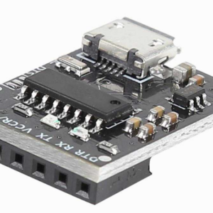
Connect a USB to TTL Serial converter to the RS232 pins.
- USB Serial TX to doctor RX
- USB Serial RX to doctor TX
- USB Serial GND to doctor GND
- Baudrate: 4800
- Parity: none
- Data bits: 8
- Stop bits: 1
Manual Mode
If you connect terminal TX pin to PCB RX pin – manual mode will be enabled automatically. You will then be able to operate the doctor manually using a terminal emulator program. (See above for terminal settings)
Expansion
The PCB can be expanded to incorporate other DIP/SMD packages using a 20 pin connector (not supplied) which will need to be soldered to the PCB.
You can then make your own adapters and connect it to the expansion port.
Consult the GitHub page and AVR datasheets on how to do this.