SD2IEC Internal
The SD2IEC is a device which emulates the IEC protocol and translates data to/from the SD card. This allows Commodore computers to read and write to SD cards rather than using floppy disks.
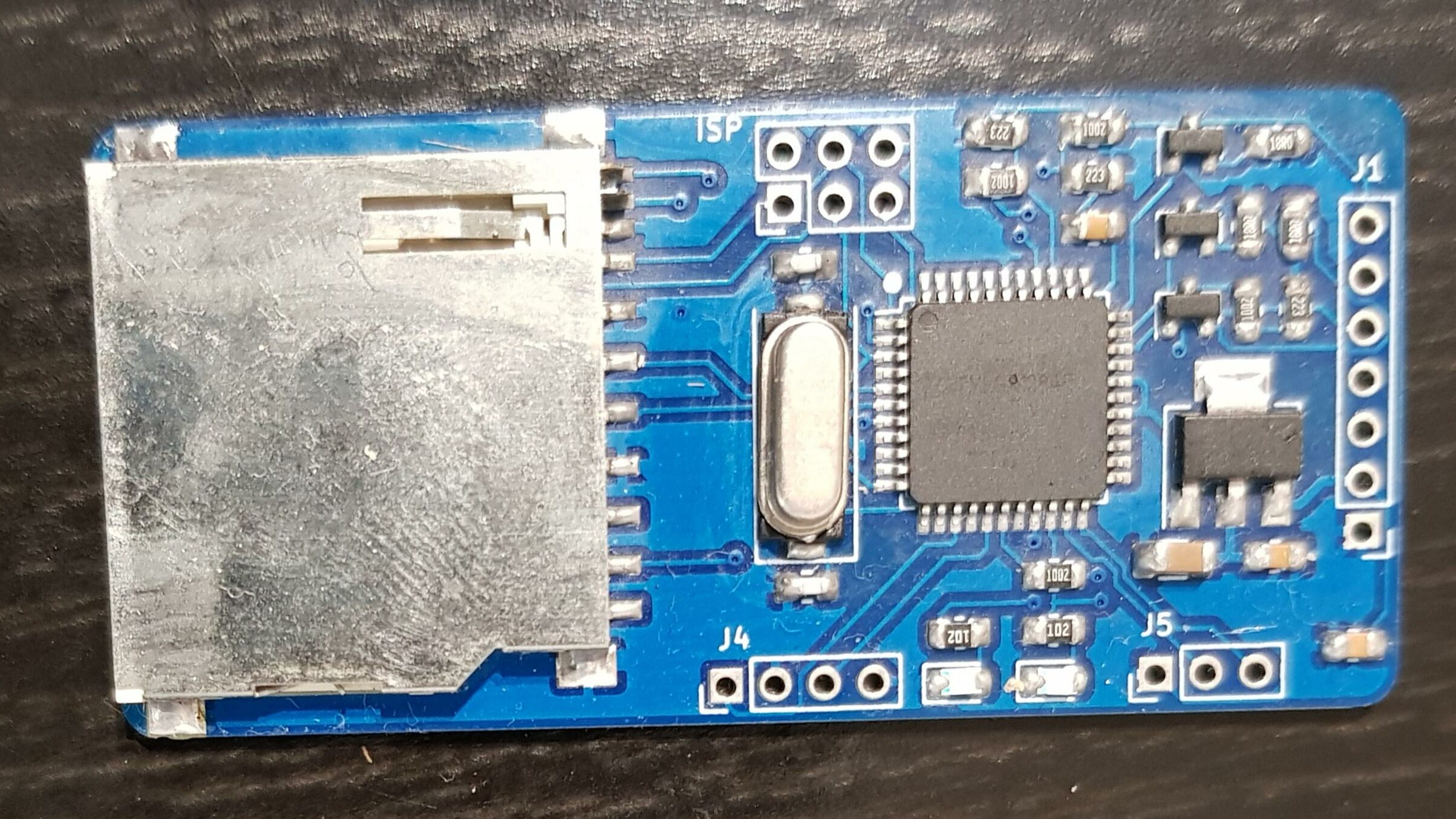
This design contains a ATmega 1284p microprocessor to allow for future (larger) software upgrades and has been miniaturized to fit inside the Commodore.
It is based on the SW2 1284p design, uses a full size SD Card slot, and has onboard Green/Red LED’s. (External LED’s can be fitted if required. Connect the LED’s through a 330R resistor)
Optional external LEDs, resistors, switches are not included.
The ATmega has been programmed and is ready for use. (Cables are not included)
PCB Size 31 x 66mm
Installation
Connector J1
- Pin 1 (Square hole) GND
- Pin 2 5V
- Pin 3 LED1 (Optional. Connect to external LED using a 330R resistor)
- Pin 4 LED2 (Optional. Connect to external LED using a 330R resistor)
- Pin 5 IEC CLK (IEC Pin 4)
- Pin 6 IEC DATA (IEC Pin 5)
- Pin 7 IEC ATN (IEC Pin 3)
Before powering on double check that the wiring is correct. Incorrect wiring can damage your computer and SD2IEC.
Configure ID (Optional)
Connector J4
- Default ID8
- Short 3-4 ID9
- Short 1-2 ID10
- Short 1-2 and 3-4 ID11
The ID can also be changed in the software, see sd2iec documentation.
Connecting buttons (Optional)
Connector J5
- Pin 1 GND
- Pin 2 PREV
- Pin 3 NEXT
Upgrading firmware
The SD2IEC hardware is based on the m1284p SW2 model.
- Download the latest binary from sd2iec.de website.
- Copy the correct bin file to the SD card.
- Power on the device. The internal LED’s (And external LED’s if fitted) will flash for a few minutes during the upgrade.
You can download the manual from here.


